Classification of drafting system in the ring frame | Explanation of a modern system

Classify the drafting systems used at the ring frame with example and explain a modern system

Drafting system can be broadly classified under two heads namely

  1. Regular drafting system without apron. And
  2. Drafting system with apron.

The system with apron can again be classified into three groups

  1. Single apron system.
  2. Double apron system. and
  3. Multiple apron system.

Example of regular drafting system without apron

  1. Conventional three roller system.
  2. Improved system.
  3. H and B four rollers long draft system.
  4. 5 over 4 roller systems.

Example of single apron drafting system

  1. Saco – Lowell. Both systems.
  2. Saco – Lowell. Shaw system.
  3. Saco – Lowell. Z system.
  4. Toenniessen system. and
  5. Versatex LS system.

Example of double apron drafting system

  1. Casablancas double apron system.
  2. Casablancas “L” system with flexible bar.
  3. Saco – Lowell thread rollers duo-Roth system.
  4. SKF pendulum top arm weighting system. And
  5. Saco – Lowell 4 – roller Duo – Roth system.

Example of multiple Apron drafting system

  1. Casablancas “N” system.
  2. Nittoh’s Semi-super high draft system.
  3. OM – S super high draft system.

OM – Super high draft system

This system is specially designed to spin direct from drawing sliver using special size small sliver cans in place of usual roving bobbin in the creels as shown in the figure below fig. –
OM-S-Super-high-draft-system

The back draft zone is in vertical position and the front zone is inclined position to 500. The rollers are spring weighted. In this system the back draft zone is equivalent to the draft of a sliver and the drafting arrangement resembles to that of the long draft sliver (Back, 4th and 3rd rollers). The front zone (3rd, 2nd, and front roller) resembles the ordinary Casablancas system.

It is claimed that, draft from 300 – 400 for count of 60s – 80s and 150 – 250 for count 20s – 40s can be obtained.

What are the functions of Ring, Traveller, Creel, Spindle, Roving guide and Lappet motion?

Ring 
The functions of ring are

  1. The ring guides the circular run of the traveller.
  2. The ring act as a high speed bearing surface for the travellers.
  3. One may also conceive the behavior of the ring as a track for the traveller.

Traveller

It performs the following functions

  1. Twisting of the drafted strand of fibres as they are delivered by the front roller to produce a yarn.
  2. Winding of yarn onto the bobbin.
  3. Maintain winding tension of the yarn by the frictional resistance between the ring and traveller.
  4. It acts as a second guide for the yarn on the way to be wound on the bobbin.
  5. It performs the function of building motion to wind the constant length of yarn delivered by the front roller. In speed frame bobbin r.p.m changes with the increase of bobbin diameter but in ring frame the bobbin r.p.m remains constant and the traveller r.p.m increases with the increase of bobbin diameter.

It also performs many other functions involving highly complicated problems of higher physics.

Creel

The function of the creel is to hold the roving bobbin over a roller beam within a convenient height to easily handle the roving. The creel must permit free running of the roving bobbins with slight tension on it.

Spindle

  1. The spindle holds the bobbin somewhat loosely but tight enough to prevent any slippage, so that the bobbin can be lifted out of the spindle with little exertion.
  2. With the help of the ring and traveller the spindle inserts twist in the yarn being delivered by the front roller.
  3. It also carries out another important function of winding the twisted thread on the bobbin with the help of ring and traveller.

Roving guide

The guides are mounted at the right angle to the flat bar called traverse bar. The object of the guide is to feed the roving correctly at the bite of the back roller and the traverse motion moves the strand almost over the entire length of the bite and this prevents the drafting rolls from being grooved at a particular place.

Lappet motion or thread board traverse

The main function of the thread board traverse is to maintain the balloon size within the controlling range. To keep the balloon length within the controlling limit, the thread board is necessarily be made to traverse relative to the ring rail. For 8” lift bobbin the traverse of the ring rail is more or less confined within the range from 1” – 1.5” and higher traverse for higher lift of the machine.

The slow traverse of lappet-rail also facilitates the easy passage of the yarn from the front roller to the bobbin.

Construction of a sewing needle

Needles have been used for hand sewing since about 18000 BC and were originally made from ivory, bone, wood and horn. Their form has remained unchanged since then. During the fifteenth century iron needles were introduced for hand sewing, and in 1800 Balthasar krems of Germany was the first to use a needle with the eye near the point for a chain-stitch machine he had developed. The large scale production of sewing machines started about 1840 and this was paralleled by numerous developments in the manufacture and quality of machine needles. Today the steel needle in common use is a precision product which is critical to the formation of stitches.

Needle-construction

The functions of the sewing machine needles are to form of a passage in the material through which the needle thread can wholly or partially pass and form a loop which can be picked up by the looper or hook mechanisms. Needles are made in straight or curved forms and their main construction features are

Butt – The truncated conical shape at the top of the needle which facilitates its insertion into the needle bar or clamp.

Shank – Usually larger in diameter than the rest of the needle, the shank can be cylindrical in shape or flat on one side, developing on the method used to secure the needle in or on the needle bar.

Shoulder – The selection joining the shank to the blade.

Blade – The longest section of the needle, this runs from the shoulder to the eye.

Grooves – On one side of the needle there is a long groove which protects the needle thread as it enters and is withdrawn from the fabric. There is a short groove on the opposite side which extends a short distance above and below the eye and its purpose is to aid the passage of the thread into the material and loop formation.

Eye – An elliptical hole between the two grooves; the shape and finish of the inside top of the eye are important factors in the prevention of thread damage during sewing.

Point – This is shaped to provide the best penetration of the material being sewn.

Tip – The tip, when combined with the point, determines the ease and extent of penetration into the fabric.

Points and tips have a decisive bearing on the performance of the needle and the various types of combinations can be divided into two groups

Round Points – These are used for the sewing of textile materials and whilst they all have a circular cross section, they differ in their tip shapes. In general, set point needles are used for most woven fabrics and the ball point needle is preferred for delicate and knitted materials. Both these points are available with light, medium or heavy tips and these combinations allow for good compatibility between the fabric and the needle.

Cutting points – These needles actually cut a hole through the material and because of this are mainly used for the sewing of leather, artificial leather and plastic materials. The points come in a variety of shapes. They all influence the set of the stitches and as a result the appearance of a row of stitches. The individual stitches are slightly slanted instead of being in a straight line.

An overview of Industrial Lock stitch/ Plain Stitch Machine

Introduction, Features, Adjustment point and Main m/c parts, Function, Maintenance, Setting, Replacement, precaution of lock stitch/plain stitch machine

Introduction: The machine which produces stitch by interlacing of threads is called lock stitch machine. This machine produces durables and is very popular in garment industry.

High-speed lock stitch sewing machine

High-speed lock stitch sewing machine

Features:

  1. Stitch is produced by interlocking.
  2. Bobbin and bobbin case are present.
  3. Threads are supplied from cone.
  4. It has only one needle.
  5. It has different type of feed mechanism.

Adjustment Point and Main Parts:

  1. Thread
  2. Tensioner
  3. Needle
  4. Stitch density
  5. Bobbin
  6. Pressure feed
  7. Needle bar
  8. Feed dog
  9. Pressure feed guide
  10. Needle plate or throught plate
  11. Spindle
  12. Bobbin case
  13. Bobbin
  14. Rotary hook
  15. Back stitch level
  16. Stitch density regulator
  17. Bobbin winding
  18. Paddle
  19. Pressure feed
  20. Pressure feed lever
  21. Side plate
  22. M/C Pulley
  23. Needle
  24. a) Needle butt
  25. b) Needle shank
  26. c) Needle eye
  27. d) Needle scarf
  28. e) Needle tip

Function: For sewing light or heavy fabric i. e. all kinds of plain sewing.
Maintenance: Maintenance can be of different types. But following types are important in this aspect:

  1. Routine maintenance: Lubrication and regular inspection is the constituent of routine maintenance. Lubrication ensures long life and safe working of all equipment’s. Inspection tries to detect faults in equipment so that repairs and replacements may be undertaken at the right time.
  2. Scheduled maintenance: This type of maintenance provides for inspection, overhaul lubrication and servicing of the machine at predetermined dates. Overhauling of the machine, cleaning of all components is normally done in this manner. It involves opening of the machine into its smallest components and carry out lubrication.

Setting: The setting of the lock stitch machine is of imminence importance. Following Setting points needs to be ensured before running the machine.

  1. Stitch density controller: It controls the no of stitches per inch. Before starting the machine, stitches per inch is determined by rotating the knob and fixing it at the desired position.
  2. Motor: Motor rpm decides the speed of the machine,. The rpm is controlled by tightening or loosing the belt over machine and motor pulley.
  3. Needle: Needle undergoes accurate setting to ensure proper sewing. Needle is attached by means of a screw which needs to be tightened enough to produce easy sewing. Again the needle size is also important from fabric point of view.
  4. Pressure foot: The type of pressure foot to be used and its proper setting is important, which is ensured by proper attachment with the moor through machine pulley.
  5. Feed dog: It is often found that due to random working the feed dog is subjected to be loose which may cause accident also. Thus the dog must be set properly with the screw.

Replacement: The replacement is revealed when the retention of equipment is no more remains an economical proposition. A replacement is affected when the equipment is subjected to compete breakage which cannot be used even after repair or it has crossed its expire date. Needle, pressure foot, feed dog etc. undergo frequent replacement.
Precaution: Following precaution must be followed when repair, setting maintenance or replacement is carried out in the lock stitch machine.

  1. All repair and maintenance work must be carried out by switching off the machine.
  2. Right tools should be used at right place.
  3. Skilled personnel should be involved for specialized job.
  4. Careful handling of all the components is necessary.
  5. The components should not be too tight or too lose.

Conclusion: It can also be called plain stitch machine. Here different sizes of needles can be used as per requirements. This machine is mostly used in our garments industries.

Definition, objects and process layout of Blow room

Blow room|Objects|Basic operations|Actions|Process layout of yarn manufacturing with a modern blow room line 

Blow room: The section where the supplied compressed cotton bale turns into a uniform lap of particular length by opening, cleaning, blending or, mixing is called blow room section. It is the first step of spinning. The section consist a number of different machines used in succession to open and clean the fibres.

Blow room machine

Objects of blow room:

  • Opening- Opening of compressed cotton bales and cotton bales are made into small tufts.
  • Cleaning- To eliminate dust, dirt, broken leaf, seed particles, grass and other foreign impurities from the fibre.
  • Blending/mixing- To produce a comparatively good quality cotton fibre by mixing different types of cotton together.
  • Lap forming

(a) To convert the opened and cleaned fibre into a sheet of particular width and uniform weight/unit length is called lap.

(b) To give a cylindrical shape to the pre determined lap by winding it in the lap pin and to make it suitable for the next process carding.

Basic operations involved in the blow room:

  • Opening- Opening is the first operation in the blow room carried out to the stage of flocks in the blow room and to the stage of individual fibres in the cards.
  • Cleaning- To remove the impurities, foreign materials and the raw materials as clean as possible.
  • Dust removal- To remove the dusts which are completely enclosed in the flocks.
  • Blending- To achieve the required quality of yarn by blending different kinds of cotton into a particular ratio.
  • Even feed of the material- To produce a lap of uniform weight per unit length or, to process the maximum quality which is suitable for carding.

Actions of blow room:

(a)   Action of opposite spike(Opening)

(b)  Action of air current(Transport Cleaning)

(c)  Action of beater and grid bar(Cleaning and opening)

(d) Action of regulating motion(Uniform output)

Process layout of yarn manufacturing system with a modern blow room line:

Bale plucker

Metal detector

Uniclean

Unimix

Uniflex

Vision shield

Condenser

Chute feed

Carding

  ↓

↓                                                            ↓

For carded yarn                                     For combed yarn

↓                                                               ↓

Breaker drawing                                    Pre-comb drawing

↓                                                                ↓

Finisher drawing                                    Lap former

↓                                                                ↓

Simplex/Roving/Speed frame            Comber

↓                                                               ↓

Ring frame                                              Post-comb drawing/Finisher drawing

↓                                                               ↓

Auto coner                                          Simplex/Roving/Speed frame

↓                                                               ↓

Heat setting                                              Ring frame

↓                                                                ↓

Packing                                                    Auto coner

Heat setting

Packing

Notes on Reactive Dyes

Q. Describe the stripping process of reactive dyed fabric with recipe.
Ans.
Stripping: Stripping becomes necessary when uneven dyeing occurs. By stripping azo groups (- N = N -) brome the dye is removed.
There are two methods of stripping such as –
· Partial stripping method.
· Full stripping method.
Partial stripping method: Partial stripping is obtained by treating the dyed fabric with dilute acetic acid or formic acid. The recommended concentration is between 5 to 10 ml glacial acid or 2.5 – 10 parts of formic acid (85%) per 1000 parts of water.
Recipe:
Glacial acetic acid — 5 – 10 gm/L
Time — 20 – 30 mins.
Temperature — 85ᵒC – 90ᵒC
Full stripping: For complete stripping, the goods are firstly treated with Sodium hydrosulphite (Na2S2O4) at boil. Then washed off and bleached at ordinary atmospheric temperature in liquor containing 1 part per 100 of commercial sodium hypochlorite.
Recipe:
Na2S2O4 — 5 gm/L
Na2CO3 — 2 gm/L
Boiling — 20 – 30 mins.
Time — 20 – 30 mins.
Temperature — Boiling

Q. Mention the function of different chemicals used in reactive dye.
Ans.
Salt: Salt acts as an electrolytic material. It helps to absorb the dye particle.
Soda Ash: Soda Ash acts as an alkali medium and it also acts as a fixing agent.
Urea: It will give deeper shade in dyeing bath. A few amount of urea will give light shade. To soluble the dye stuff properly urea is used.
Sodium alginate: It is a thickening agent. It is collected from sea – weeds. It helps to bind the dye materials in their position. It will also act as a fixing agent

Q. Why Soaping is necessary after dyeing?
Ans. We use different types of dyes in the dye bath. Maximum cases dye stuffs are sedimented (তলানি) on the bottom of the dye bath and deposited on the textile material we use soaping method to increase the brightness and to remove the floated color we use soaping process.

Q. Mention the use of salt & soda ash in reactive dye for different shade.
Ans.
Shade
Salt (g/L)
Soda Ash (g/L)
Light shade
37
12
Medium shade
60
15
Deep shade
80
20

Q. Write down the application of reactive dyes on cotton goods.
Ans. Now – a – days reactive dyes are popularly used for cotton goods. Generally 4 types of cotton goods are used to dye with the reactive dye –
i. Loose fiber form.
ii. Yarn form.
iii. Knit goods
iv. Woven fabric.
Jigger dyeing m/c (Woven fabric), Winch dyeing m/c (Knitted fabric) and Jet dyeing m/c (Knitted + Woven)

Q. Write down the test method of reactive dye.
Ans.
Recipe:
H2SO4 — 1 cc/litre of water
Na2S2O4 — 2 cc/litre of water
M: L — 1:20
Temp. — Up to boiling
Time — 30 mins.
ü When a sample of reactive dyed fabric is treated in a test tube containing H2SO4 of 1 cc per 1 litre water, it results bleaching of reactive color from the dyed fabrics. It is one of the identification tests of reactive color.
ü The reactive color remains fixed on the textile material though it is treated or boiled with pyridine or chloroform. On the other hand, textile material dyed with direct, azoic etc. dye stuffs and treated with above chemicals then color will come out easily. It is one of the identification tests of reactive color.
The second one is one of the most efficient test methods of reactive dye.

Q. Write down the classification of reactive dye with example.
Ans.
1 On the basis of reactive group: Two types;
Halogen added group (Cl 2, F2, Br2,I2)
Example: Pyrimidine.
Vinyl added group (– CH = CH2)
(– D – SO2 – NH – CH = CH2) [– CH = CH2 ……….Reactive group]
Example: Levafix.
2 On the basis of reactivity: Three types;
High reactivity. Ex. Procion – E. {Medium alkali (NaHCO3) used}.
Moderate reactivity. Ex. Livafix – E. {Medium alkali (Na2CO3) used}.
Low reactivity. Ex. Premazine. {Strong alkali (NaOH) used}.
3 On the basis of use: Two types;
Cold brand reactive dyes (High reactivity) – 40ᵒC – 50ᵒC
Hot brand reactive dyes (Low reactivity) – 90ᵒC – 95ᵒC
Use of Hot brand is maximum in our country, Cold brand is used for batik, tye dye etc.

Q. Mention the reactive dyeing methods.
Ans.
Ø Batch dyeing method (Discontinuous method):
· Hot brand Dye.
· Cold brand Dye.
Ø Continuous method:
· Pad system method.
· Pad thermo fixation method.
Ø Semi – continuous method:
· Pad roll method
· Pad – jigger method.

Q. Describe the Cold Brand dyeing with reactive dye.
Ans.
Recipe:
Dye stuff —- 3% (According to the wt of mlts)
Soda Ash —- 15 gm/L
H2O —- 10 times
Temperature —- 40ᵒC
Salt —- 60 gm/L
Time —- 1 Hour
Dyeing scheme:

At first solubulize the dye stuff with a little amount of cold water. Take required water to the dye bath.
Procedure:
At first solubulize the dye stuff with a little amount of cold water. Take required water to the dye bath. Dye liquor and salt is given to the dye bath and stirred (নাড়ানো) throughly. Then the textile material is taken to the dye bath and dyed for 20 – 30 mins. After dyeing the material is rinsed (পরিষ্কার পানি দিয়ে ধোয়া) with cold water. Then treated with 20% soap and 1% soda solution in a bath for 30 minutes, then the material is washed and dried.

What is Fiber Fusion?

Fiber Fusion is 2 days of fiber, education and fun!  Whether you are new to the world of natural fibers or are an experienced fiber aficionado – Fiber Fusion has something for you!

There will be fabulous fleeces – alpaca, wool, mohair, llama and angora – at our fleece shows and sales, as well as free demonstrations throughout the weekend, a wide variety of classes, over 60 fiber-related vendors, a live fiber animal exhibit, a fiber arts contest, people’s choice photo contest, a spin-in and much more!

Carbon Fiber | Characteristics/Properties of Carbon Fibers | Classification of Carbon Fiber | Application/Uses of Carbon Fibers

Carbon Fiber:
Weave of Carbon fiber
Carbon fiber is a high-tensile fiber or whisker made by heating rayon or polyacrylonitrile fibers or petroleum residues to appropriate temperatures. Fibers may be 7 to 8 microns in diameter and are more that 90% carbonized.This fibers are the stiffest and strongest reinforcing fibers for polymer composites, the most used after glass fibers. Made of pure carbon in form of graphite, they have low density and a negative coefficient of longitudinal thermal expansion.
Carbon fibers are very expensive and can give galvanic corrosion in contact with metals. They are generally used together with epoxy, where high strength and stiffness are required, i.e. race cars, automotive and space applications, sport equipment.

Depending on the orientation of the fiber, the carbon fiber composite can be stronger in a certain direction or equally strong in all directions. A small piece can withstand an impact of many tons and still deform minimally. The complex interwoven nature of the fiber makes it very difficult to break.
Characteristics/Properties of Carbon Fibers 

  1. Physical strength, specific toughness, light weight.
  2. Good vibration damping, strength, and toughness.
  3. High dimensional stability, low coefficient of thermal expansion, and low abrasion.
  4. Electrical conductivity.
  5. Biological inertness and x-ray permeability.
  6. Fatigue resistance, self-lubrication, high damping.
  7. Electromagnetic properties.
  8. Chemical inertness, high corrosion resistance.

Classification of Carbon Fiber:
Based on modulus, strength, and final heat treatment temperature, carbon fibers can be classified into the following categories:

  1. Based on carbon fiber properties,
  2. Based on precursor fiber materials,
  3. Based on final heat treatment temperature,

1. Based on carbon fiber properties, carbon fibers can be grouped into:

  • Ultra-high-modulus, type UHM (modulus >450Gpa)
  • High-modulus, type HM (modulus between 350-450Gpa)
  • Intermediate-modulus, type IM (modulus between 200-350Gpa)
  • Low modulus and high-tensile, type HT (modulus 3.0Gpa)
  • Super high-tensile, type SHT (tensile strength > 4.5Gpa)

2. Based on precursor fiber materials, carbon fibers are classified into:

  • PAN-based carbon fibers
  • Pitch-based carbon fibers
  • Mesophase pitch-based carbon fibers
  • Isotropic pitch-based carbon fibers
  • Rayon-based carbon fibers
  • Gas-phase-grown carbon fibers

3. Based on final heat treatment temperature, carbon fibers are classified into: 

  • High-heat-treatment carbon fibers (HTT), where final heat treatment temperature should be above 2000°C and can be associated with high-modulus type fiber.
  • Intermediate-heat-treatment carbon fibers (IHT), where final heat treatment temperature should be around or above 1500°C and can be associated with high-strength type fiber.
  • Low-heat-treatment carbon fibers, where final heat treatment temperatures not greater than 1000°C. These are low modulus and low strength materials.
Application/Uses of Carbon Fiber
The two main applications of carbon fibers are in specialized technology, which includes aerospace and nuclear engineering, and in general engineering and transportation, which includes engineering components such as bearings, gears, cams, fan blades and automobile bodies. Recently, some new applications of carbon fibers have been found. Such as rehabilitation of a bridge in building and construction industry. Others include: decoration in automotive, marine, general aviation interiors, general entertainment and musical instruments and after-market transportation products. Conductivity in electronics technology provides additional new application.
Application Carbon Fiber are given as Shortly:

  • Aerospace, road and marine transport, sporting goods.
  • Missiles, aircraft brakes, aerospace antenna and support structure, large telescopes, optical benches, waveguides for stable high-frequency (GHz) precision measurement frames.
  • Audio equipment, loudspeakers for Hi-fi equipment, pickup arms, robot arms.
  • Automobile hoods, novel tooling, casings and bases for electronic equipments, EMI and RF shielding, brushes.
  • Medical applications in prostheses, surgery and x-ray equipment, implants, tendon/ligament repair.
  • Textile machinery, genera engineering.
  • Chemical industry; nuclear field; valves, seals, and pump components in process plants.
  • Large generator retaining rings, radiological equipment.

Carbon fibre is sometimes used in conjunction with fiberglass because of their similar manufacturing processes, an example of this would be the Corvette ZO6 where the front end is carbon fibre and the rear is fibreglass. Carbon fiber is however, far stronger and lighter than fiberglass.

Carbon fibre can be found in a wide range of performance vehicles including sports cars, superbikes, pedal bikes (where they are used to make frames), powerboats and it is often used in the tuning and customising industry where attractive woven panels are left unpainted to ‘show off’ the material.

Introduction of Glass Fiber | Types of Glass Fiber | Properties of Glass Fiber | Manufacturing Processes of Glass Fiber | Uses of Glass Fiber or Glass Yarn

Glass fiber also called fiberglass. It is material made from extremely fine fibers of glass Fiberglass is a lightweight, extremely strong, and robust material. Although strength properties are somewhat lower than carbon fiber and it is less stiff, the material is typically far less brittle, and the raw materials are much less expensive. Its bulk strength and weight properties are also very favorable when compared to metals, and it can be easily formed using molding processes. Glass is the oldest, and most familiar, performance fiber. Fibers have been manufactured from glass since the 1930s.


e7929-product5

           Fig : Glass fiber

Types of Glass Fiber 
As to the raw material glass used to make glass fibres or nonwovens of glass fibres, the following classification is known:

1. A-glassWith regard to its composition, it is close to window glass. In the Federal Republic of Germany it is mainly used in the manufacture of process equipment.

2. C-glass: This kind of glass shows better resistance to chemical impact.

3. E-glass: This kind of glass combines the characteristics of C-glass with very good insulation to electricity.

4. AE-glass: Alkali resistant glass.

Generally, glass consists of quartz sand, soda, sodium sulphate, potash, feldspar and a number of refining and dying additives. The characteristics, with them the classification of the glass fibres to be made, are defined by the combination of raw materials and their proportions. Textile glass fibres mostly show a circular

Properties of Glass Fiber
Glass fibers are useful because of their high ratio of surface area to weight. However, the increased surface area makes them much more susceptible to chemical attack. By trapping air within them, blocks of glass fiber make good thermal insulation, with a thermal conductivity of the order of 0.05 W/(mK).

The strength of glass is usually tested and reported for “virgin” or pristine fibers those which have just been manufactured. The freshest, thinnest fibers are the strongest because the thinner fibers are more ductile. The more the surface is scratched, the less the resulting tenacity. Because glass has an amorphous structure, its properties are the same along the fiber and across the fiber. Humidity is an important factor in the tensile strength. Moisture is easily adsorbed, and can worsen microscopic cracks and surface defects, and lessen tenacity.

In contrast to carbon fiber, glass can undergo more elongation before it breaks. There is a correlation between bending diameter of the filament and the filament diameter. The viscosity of the molten glass is very important for manufacturing success. During drawing (pulling of the glass to reduce fiber circumference), the viscosity should be relatively low. If it is too high, the fiber will break during drawing. However, if it is too low, the glass will form droplets rather than drawing out into fiber.

Glass Fiber Manufacturing Processes
After the initial process of melting glass and passing it through spinnerets, continuous filaments or staple fibers of glass are manufactured by two different methods.

Continuous Filament Process
In this process, continuous filaments of indefinite length is produced. The molten glass passes through spinnerets having hundreds of small openings. These strands of multiple filaments are carried to winder revolving at very high speed of more than 2 miles per km. This process draws out the fibers in parallel filaments of the diameter of the openings. A sizing or a binder is applied to facilitate the twisting and winding process and to prevent breakage during yarn formation. After winding, filaments are further twisted and plied to make yarns by methods similar to those for making other continuous filament yarns. The sizing is removed through volatizing in an oven. These yarns are used for making such items as curtains and drapes.

Staple Fiber Process
Fibers with long-staple qualities are manufactured through staple fiber process. There are many methods for producing such fibers.

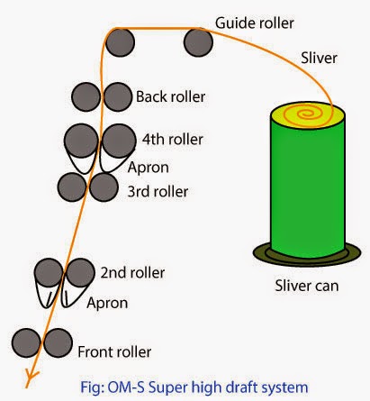
In one of such methods, the molten glass flows through the small holes of bushing, where jets of compressed air shake the thin streams of molten glass into fine fibers. These fibers vary in length ranging from 8 to 15 inches. The fibers fall through a spray of lubricant and a drying flame onto e revolving drum where they form into a thin web. These fibers in the form of web are gathered from the drum into a sliver. Yarn is then made from this sliver by similar methods that are adopted for making cotton or wool yarns. These yarns are used for fabrics for industrial purposes where insulation is required.

In yet another method, the ends of the glass rods are melted from which drops of glass fall away drawing off glass filaments after them onto a speedily revolving cylinder where they are wound parallel to each other. A web of sliver is formed if the cylinder moves sideways. Sometimes, the staple may be thrown off the cylinder onto a stationary sieve where it forms a sliver. In either conditions, the sliver is then converted into spun yarn.

The staple fiber, if subjected to oven, is compressed to the desired thickness and the binder which was earlier applied, is cured. This permanently binds the fibers.

Production:
The subsequent manufacture of glass fibres may be executed to the direct melting process. However, in most cases glass rods or balls are made first which then may undergo a variety of further processes.

Nozzle-Drawing:
As can be seen in Fig. 1-50, the glass fed in is melted in a heated melt tub at 1250–1400oC. Then, it emerges at the bottom of the melt tub from nozzle holes of 1–25 mm diameter and it is taken off and drawn. The filaments solidify and are finished and wound. One can find them in the shops as various kinds of “glass silk”. To make them into webs, the filaments are cut to length (mostly, between 6 and 25 mm).

Manufacture of glass melt
Processes to make glass fibres
Nozzle-Blowing: 
The same as with nozzle-drawing, glass balls are melted in the tub. The melt emerging from the nozzle holes is then taken by pressed air, which draws the liquid glass so as to make fibres of 6–10 um diameter. A fluttering effect is caused by the flow of pressed air, which results in fibres of lengths from 50 to 300 mm. A lubricant is put on and the fibres are laid down on a sieve drum which sucks them in. The dry web received is held together by the long fibres, the short ones lying in between them as a filling material. Then, the slivers of glass fibre material are cut.Rod-Drawing: 
By means of a burner, bundles of glass rods are melted at their bottom ends. This results in drops which, as they fall down, draw filaments after them. The filaments are taken by a rotating drum, a squeegee laying them down onto a perforated belt. Thus, a dry web is received which can be wound as glass fibre slivers. – Machine performance being limited by the number of glass rods fed in, the rotating drum may be combined with nozzle-drawing, which results in drum-drawing. This multiplies machine performance. The dry web is again laid down onto a perforated belt and solidified or, after winding it so as to receive slivers, cut for further processing on machines producing wetlaid nonwovens. Using and processing glass fibres is not without any problems. For example, fine pieces of broken fibres may disturb if the work place is not well prepared for the purpose. Using the nonwovens to manufacture glass-fibre reinforced plastics, it is important the surface of the plastic material is fully even. Ends of fibre looking out may be pulled out or loosened by outward stress (temperature, gases, liquids), which may influence material characteristics. In some cases, it is
advisable to cover up such layers of glass fibre with suitable chemical fibres.Uses of Glass Fiber or Glass Yarn
Glass fiber is manufactured in a wide range of fine diameters. Some of them are so fine that they can be seen only through a microscope. This quality of fineness contributes greatly to the flexibility of glass fibers. Various manufacturers produce different types of glass fibers for different end uses. Glass fibers them are used for various purpose.

  1. For making home furnishings fabrics;
  2. For making apparels and garments; and
  3. For the purpose tires and reinforced plastics.

There are certain glass fibers that can resist heat upto 7200oC and can withstand forces having speed of 15,000 miles per hour. These types of glass fibers are used as

  1. Filament windings around rocket cases;
  2. Nose cones;
  3. Exhaust nozzles; and
  4. Heat shields for aeronautical equipment

Some other types of glass fibers are embedded into various plastics for strength. These are used in

  1. Boat hulls and seats;
  2. Fishing rods; and
  3. Wall paneling

Some other types of glass fibers are used for reinforcing electrical insulation. Yet other types are used as batting for heat insulation in refrigerators and stoves.